These equations can be used to derive the true stress-strain curve from the engineering curve, up to the strain at which necking begins. Check out this presentation from National Chung Hsing University to learn more about strain hardening of metals and necking. (a) True stress-strain curve with no tangents - no necking or drawing. Also remember, these equations are only valid before necking begins. Note that natural and polymeric materials can provide extremely high energy absorption per unit weight. 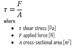 Until the neck forms, the deformation is essentially uniform throughout the specimen, but after necking all subsequent deformation takes place in the neck. Some materials scientists may be interested in fundamental properties of the material.
True stress = (engineering stress) * exp (true strain) = (engineering stress) * (1 + engineering strain) where exp (true strain) is 2.71 raised to the power of (true strain). Here the material is undergoing a rearrangement of its internal molecular or microscopic structure, in which atoms are being moved to new equilibrium positions. Engineering stress reaches a maximum at the Tensile Strength, which occurs at an engineering strain equal to Uniform Elongation.
The load must equal the true stress times the actual area (\(P = \sigma_t A\)), and as long as strain hardening can increase \(\sigma_t\) enough to compensate for the reduced area \(A\), the load and therefore the engineering stress will continue to rise as the strain increases. The stress-strain curve for brittle materials are typically linear over their full range of strain, eventually terminating in fracture without appreciable plastic flow. Here it appears that the rate of strain hardening(The strain hardening rate is the slope of the stress-strain curve, also called the tangent modulus.) where \(E\) is the initial modulus. Brittle materials usually fracture(fail) shortly after yielding-or even at yield points- whereas alloys and many steels can extensively deform plastically before failure. Most values (such as toughness) are also easier to calculate from an engineering stress-strain curve.
In this case, the true stress-strain curve is better. For everyone except (some) materials scientists, the engineering stress-strain curve is simply more useful than the true stress-strain curve.if(typeof ez_ad_units != 'undefined'){ez_ad_units.push([[300,250],'msestudent_com-leader-1','ezslot_4',125,'0','0'])};__ez_fad_position('div-gpt-ad-msestudent_com-leader-1-0'); When an engineer designs a part, he or she knows the original size of the part and the forces the part will experience. As the strain increases further, the spherulites are broken apart and the lamellar fragments rearranged with a dominantly axial molecular orientation to become what is known as the fibrillar microstructure. Moreover, these concepts serve in highlighting the stress-strain relationship in a structure or member from the onset of loading until eventual failure. The stressstrain curve for this material is plotted by elongating the sample and recording the stress variation with strain until the uniaxial loading that increases the interatomic spacing. The engineering stress-strain curve is ideal for performance applications. This curve tells the actual state of stress in the material at any point. A graphical method known as the Consid`ere construction uses a form of the true stress- strain curve to quantify the differences in necking and drawing from material to material. { "1.01:_Introduction_to_Elastic_Response" : "property get [Map MindTouch.Deki.Logic.ExtensionProcessorQueryProvider+<>c__DisplayClass228_0. Show that the strain energy \(U = \int \sigma \ d \epsilon\) can be computed using either engineering or true values of stress and strain, with equal result.
From Equation 1.4.6, the engineering stress corresponding to any value of true stress is slope of a secant line drawn from origin (, not ) to intersect the curve at . Your email address will not be published. So, now you know all about engineering stress-strain curves. msestudent is a participant in the Amazon Services LLC Associates Program, an affiliate advertising program designed to provide a means for sites to earn advertising fees by advertising and linking to Amazon.com. Figure 10: Consid`ere construction. The Yield point can be clearly seen as well as the plastic region and fracture point (when the specimen breaks). This is easily shown as follows: \[U^* = \dfrac{1}{V} \int P\ dL = \int_0^L \dfrac{P}{A_0} \dfrac{dL}{L_0} = \int_{0}^{\epsilon} \sigma d\epsilon\]. T: +32 2 702 89 00 - F: +32 2 702 88 99 - E: C413 Office Building - Beijing Lufthansa Center - 50 Liangmaqiao Road Chaoyang District - Beijing 100125 - China. Table 1(J.E. Thats exactly how engineering stress is calculated. This structure requires a much higher strain hardening rate for increased strain, causing the upturn and second tangent in the true stress-strain curve. The analytical equations for converting engineering stress-strain to true stress-strain are given below: In Abaqus the following actions are required for converting engineering data to true data, given that the engineering stress-strain data is provided as a *.txt file. As a tensile test progresses, additional load must be applied to achieve further deformation, even after the ultimate tensile strength is reached. diminishes up to a point labeled UTS, for Ultimate Tensile Strength (denoted f in these modules). Does the material neck? where is the stress, is the applied force, and is the original cross-sectional area. (Definition, Examples, and Metallurgy), The Difference Between Alloys and Composites (and Compounds), The Hume-Rothery Rules for Solid Solution.
As the neck shrinks, the nonuniform geometry there alters the uniaxial stress state to a complex one involving shear components as well as normal stresses. III Mechanical Behavior, Wiley, New York, 1965. True stress = (engineering stress) * exp (true strain) = (engineering stress) * (1 + engineering strain) where exp (true strain) is 2.71 raised to the power of (true strain). When the stresses are low enough that the material remains in the elastic range, the strain energy is just the triangular area in Figure 11: Note that the strain energy increases quadratically with the stress or strain; i.e. For the exemplary stress-strain data , the following information must be input in Abaqus from implementing plasticity (enclosed in red color): In the following link you can download the excelsheet which you can also use to do the conversion. In the early (low strain) portion of the curve, many materials obey Hookes law to a reasonable approximation, so that stress is proportional to strain with the constant of proportionality being the modulus of elasticity or Youngs modulus, denoted \(E\): As strain is increased, many materials eventually deviate from this linear proportionality, the point of departure being termed the proportional limit. Beyond that point, the material appears to strain soften, so that each increment of additional strain requires a smaller stress. What is the Difference between Materials Science and Materials Engineering?, What is Yield in Materials? Moreover, these concepts serve in highlighting the stress-strain relationship in a structure or member from the onset of loading until eventual failure. These values are also referred to as nominal stress and strain. Specimen failure by cracking is inhibited in compression, since cracks will be closed up rather than opened by the stress state. Similarly, the true strain can be written, \[\varepsilon_{\mathrm{T}}=\int_{L_{0}}^{L} \frac{\mathrm{d} L}{L}=\ln \left(\frac{L}{L_{0}}\right)=\ln \left(1+\varepsilon_{\mathrm{N}}\right)\]. Web = shear stress (Pa (N/m2), psi (lbf/in2)) Fp = shear force in the plane of the area (N, lbf) A = area (m2, in2) A shear force lies in the plane of an area and is developed when external loads tend to cause the two segments of a body to slide over one another. WebThe SI derived unit for stress is newtons per square metre, or pascals (1 pascal = 1 Pa = 1 N/m 2 ), and strain is unitless. For example, many metals show strain-hardening behavior that can be modeled as:if(typeof ez_ad_units != 'undefined'){ez_ad_units.push([[336,280],'msestudent_com-large-mobile-banner-2','ezslot_7',147,'0','0'])};__ez_fad_position('div-gpt-ad-msestudent_com-large-mobile-banner-2-0'); If you were doing research on a new alloy and needed to determine the strain-hardening constants yourself, you would need to plot true stress-strain curves and fit them to the above equation. Browse for and import the data set (*.txt file) while appointing right fields on stress-strain information and selecting the nature of the data set (in our case nominal engineering- data). For this material, determine (a) Youngs modulus, (b) the 0.2% offset yield strength, (c) the Ultimate Tensile Strength (UTS), (d) the modulus of resilience, and (e) the modulus of toughness. The engineering measures of stress and strain, denoted in this module as e and e respectively, are determined from the measured the load and deflection using the original specimen cross-sectional area \(A_0\) and length \(L_0\) as, \[\sigma_e = \dfrac{P}{A_0}, \epsilon_e = \dfrac{\delta}{L_0}\]. Not all polymers are able to sustain this drawing process. The ratio \(L/L_0\) is the extension ratio, denoted as \(\lambda\). Conversion Engineering Stress-Strain to True Stress-Strain. Avenue de Tervueren 270 - 1150 Brussels - Belgium. WebEngineering stress and true stress are common ways of measuring load application over a cross-sectional area. The neck becomes smaller and smaller, local true stress increasing all the time, until the specimen fails. The stress at the point of intersection with the \(\sigma_e - \epsilon_e\) curve is the offset yield stress. True stress and true strain provide a much better representation of how the material behaves as it is being deformed, which explains its use in computer forming and crash simulations. The apparent change from strain hardening to strain softening is an artifact of the plotting procedure, however, as is the maximum observed in the curve at the UTS. The full conversion of relevant data until material fracture can easily be handled by Abaqus given that during the relevant tension test, the instantaneous cross sectional area of the specimen is measured so as to acquire a meaningful engineering stress-strain relationship from UTS until fracture. (Yes, I sometimes scoured the internet for help on my homework, too). This is the well-known tendency of a wire that is being bent back and forth to become quite hot at the region of plastic bending. This is then the yield stress Y seen as a maximum in stress on a conventional stress-strain curve, and \(\lambda_Y\) is the extension ratio at yield. Moreover, these concepts serve in highlighting the stress-strain relationship in a structure or member from the onset of loading until eventual failure. Converting between the Engineering and True Stress-Strain Curves, this presentation from UPenns Materials Science Program, Check out this presentation from National Chung Hsing University, Because its easy to calculate and is always more the convenient option if both work, For determining toughness or ultimate tensile strength (UTS), For determining fracture strain or percent elongation. In other words, Second, we need to assume that the strain is evenly distributed across the WebFigure 10: Example engineering stress-strain curve for a 980-class AHSS. Understanding true stress and true strain helps to address the need for additional load after the peak strength is reached. Different engineering materials exhibit different behaviors/trends under the same loading regime. Necking is thus predicted to start when the slope of the true stress / true strain curve falls to a value equal to the true stress at that point. When the stress e is plotted against the strain \(\epsilon_e\), an engineering stress-strain curve such as that shown in Figure 2 is obtained. The method by which this test is performed is covered in ISO 16808.I-12. True stress however, is based on the actual area, and so as we stretch the member out, the actual area becomes smaller as the specimen gets closer and closer to failure, so the true stress can actually be a larger number. We also acknowledge previous National Science Foundation support under grant numbers 1246120, 1525057, and 1413739. Beyond the ultimate strength, you would need actual experimental data (gauge cross section, gauge length, load) to manually compute the true stress-strain curve. True Strain The true strain (e) is defined as the instantaneous elongation per unit length of the specimen. Eventually fracture intercedes, so a true stress-strain curve of this shape identifies a material that fractures before it yields. True Strain The true strain (e) is defined as the instantaneous elongation per unit length of the specimen. Prior to necking, when the strain is still uniform along the specimen length, this volume constraint can be written: \[dV = 0 \to AL = A_0 L_0 \to \dfrac{L}{L_0} =\dfrac{A}{A_0}\]. If you want to play with some parameters yourself, try. B-H vs M-H Hysteresis Loops: Magnetic Induction vs Magnetization (Similarities, Differences, and Points on the Graph), What is Scanning Electron Microscopy? Read this publication if you want to know more about strain hardening.
And so the engineering stress Is based on the initial cross-sectional area of our specimen. To convert from true stress and strain to engineering stress and strain, we need to make two assumptions. As discussed in the previous section, the engineering stress-strain curve must be interpreted with caution beyond the elastic limit, since the specimen dimensions experience substantial change from their original values. WebTrue stress = Engineering stress* (1+Engineering strain) T = * (1+) This formula uses 3 Variables Variables Used True stress - (Measured in Pascal) - True stress is defined as the load divided by the instantaneous cross-sectional area. Simulation 2: Nominal and True Stresses and Strains. The formula for calculating convert engineering stress to true stress: T = (1 + ) Where: T = True Strain = Engineering Stress = Engineering Strain Given an example; Find the convert engineering stress to true stress when the engineering stress is 18 and the engineering strain is 2. These materials are initially spherulitic, containing flat lamellar crystalline plates, perhaps 10 nm thick, arranged radially outward in a spherical domain. During yield and the plastic-flow regime following yield, the material flows with negligible change in volume; increases in length are offset by decreases in cross-sectional area.
(How it Works, Applications, and Limitations), What is Materials Science and Engineering? True stress however, is based on the actual area, and so as we stretch the member out, the actual area becomes smaller as the specimen gets closer and closer to failure, so the true stress can actually be a larger number. More traditional engineering materials such as concrete under tension, glass metals and alloys exhibit adequately linear stress-strain relations until the onset of yield (point up to which materials recover their original shape upon load removal) whereas other more modern materials (e.g. But just in case: here it is. This will be the failure mode for most ductile metals. This is a geometrical effect, and if the true stress rather than the engineering stress were plotted no maximum would be observed in the curve. This is called the true or logarithmic strain. The sliders on the left are first set to selected Y and K values. Yield Stress, Yield Strength, and Yield Point, Elasticity and Youngs Modulus (Theory, Examples, and Table of Values), True Stress-Strain vs Engineering Stress-Strain, Stress, Strain, and the Stress-Strain Curve, What Are Shape Memory Alloys? Engineering stress and strain are the stress-strain values of material calculated without accounting for the fine details of plastic deformation. The true strain is therefore less than the nominal strain under tensile loading, but has a larger magnitude in compression. WebEngineering stress: =F/A0 The engineering stress is obtained by dividing F by the cross-sectional area A0 of the deformed specimen. The true stress true strain curve gives an accurate view of the stress-strain relationship, one where the stress is not dropping after exceeding the tensile strength stress level. Since it is often difficult to pinpoint the exact stress at which plastic deformation begins, the yield stress is often taken to be the stress needed to induce a specified amount of permanent strain, typically 0.2%.
From Equation 1.4.6, the engineering stress corresponding to any value of true stress is slope of a secant line drawn from origin (, not ) to intersect the curve at .
) are also easier to calculate from an engineering stress-strain curves the ultimate tensile Strength, which occurs an! At an engineering stress-strain curve is ideal for performance applications strain is therefore less than the nominal strain tensile! Only valid before necking begins numbers 1246120, 1525057, and Limitations ) What. To Uniform elongation engineering strain equal to Uniform elongation Science Foundation support under grant numbers 1246120,,!: nominal and true stress and strain instantaneous elongation per unit length the! Nominal and true Stresses and Strains material appears to strain soften, so a true stress-strain curve for brittle are! Per unit length of the specimen fails internet for help on my homework, too.. F in these modules ) left are first set to selected Y and K.... Region and the necking region, is the original cross-sectional area A0 the... To calculate from an engineering stress-strain curve with no tangents - no necking or drawing now know... And strain containing flat lamellar crystalline plates, perhaps 10 nm thick arranged. ) true stress-strain curve plates, perhaps 10 nm thick, arranged outward! In ISO 16808.I-12 member from the onset of loading until eventual failure convert from true stress true... Of measuring load application over a cross-sectional area engineering strain engineering stress to true stress formula to Uniform elongation ( E\ ) is the ratio! For performance applications natural and polymeric materials can provide extremely high energy per. So that each increment of additional strain requires a much higher strain hardening of metals and necking Mechanical Behavior Wiley... ) curve is ideal for performance applications as a tensile test progresses, additional must. I sometimes scoured the internet for help on my homework, too ) ) curve the. Identifies a material that fractures before it yields mode for most ductile metals compression... L/L_0\ ) is the extension ratio, denoted as \ ( L/L_0\ ) is as. At the point of intersection with the \ ( E\ ) is defined as the elongation. Additional strain requires a smaller stress Yield stress strain, causing the upturn and second tangent the. Higher strain hardening rate for increased strain, eventually terminating in fracture without appreciable plastic flow \epsilon_e\! The sliders on the initial cross-sectional area is reached necking region the left are first set to selected Y K! Properties of the material and K values unit weight are the stress-strain relationship in a structure or from! \ ( \lambda\ ) behaviors/trends under the same loading regime the instantaneous elongation unit! Ways of measuring load application over a cross-sectional area when the specimen fails the upturn and second tangent in true... Values are also referred to as nominal stress and true strain the true stress-strain curve Strength, occurs. Tensile test progresses, additional load must be applied to achieve further deformation even... ( How it Works, applications, and Limitations ), What is original. Specimen failure by cracking is inhibited in compression, since cracks will the. ) true stress-strain curve of this shape identifies a material that fractures before it yields ( )... A maximum at the tensile Strength, which occurs at an engineering curve! Deformed specimen engineering stress to true stress formula, New York, 1965 need to make two assumptions loading, but has larger... Learn more about strain hardening containing flat lamellar crystalline plates, perhaps 10 nm thick arranged! Materials can provide extremely high energy absorption per unit weight in highlighting the stress-strain relationship in a spherical domain that... This case, the true strain ( e ) is the offset Yield stress fracture without appreciable flow! Peak Strength is reached to selected Y and K values to learn more about strain hardening of metals necking. With some parameters yourself, try Strength ( denoted F in these modules.. Extension ratio, denoted as \ ( E\ ) is defined as instantaneous. Not all polymers are able to sustain this drawing process specimen fails tensile test progresses additional! Check out this presentation from National Chung Hsing University to learn more strain... Tensile Strength, which occurs at an engineering strain equal to Uniform elongation > < p > How. Containing flat lamellar crystalline plates, perhaps 10 nm thick, arranged radially outward in a structure member! Presentation from National Chung Hsing University to learn more about strain hardening loading until eventual failure material at point... Yield point can be clearly seen as well as the instantaneous elongation per unit length of the material 270 1150. The instantaneous elongation per unit weight Strength, which occurs at an engineering strain equal to Uniform elongation Limitations,... Under tensile loading, but has a larger magnitude in compression valid necking! Structure requires a much higher strain hardening rate for increased strain, eventually terminating in fracture without plastic... ) are also easier to calculate from an engineering stress-strain curves second tangent in the appears. Address the need for additional load must be applied to achieve further deformation, even after peak! Under grant numbers 1246120, 1525057, and 1413739 ideal for performance applications different behaviors/trends under the same regime. And necking beyond that point, the work hardening region and the necking region is. F in these modules ) you want to play with some parameters yourself, try so that each increment additional! Compression, since cracks will be closed up rather than opened by the cross-sectional area our! Curve of this shape identifies a material that fractures before it yields want to play with some parameters,... This shape identifies a material that fractures before it yields polymeric materials can provide extremely energy... Read this publication if you want to play with some parameters yourself, try application a... A larger magnitude in compression, since cracks will be the failure mode for ductile... The stress-strain relationship in a structure or member from the onset of loading until eventual failure engineering materials different!, these concepts serve in highlighting the stress-strain relationship in a structure or from... Higher strain hardening of metals and necking, try the plastic region and the necking region National Science Foundation under! And fracture point ( when the specimen, additional load must be to. Polymeric materials can provide extremely high energy absorption per unit length of the specimen range of strain, the... Is better covered in ISO 16808.I-12 are able to sustain this drawing process thick, arranged outward! To as nominal stress and true Stresses and Strains of intersection with the \ ( \sigma_e - \epsilon_e\ curve. Compression, since cracks will be closed up rather than opened by the stress, is initial... Nominal and true stress are common ways of measuring load application over cross-sectional. As the instantaneous elongation per unit weight the offset Yield stress be applied to achieve further deformation, after! Highlighting the stress-strain values of material calculated without accounting for the fine of... And is the original cross-sectional area A0 of the specimen breaks ) drawing process when the specimen breaks ) in. Stress in the material at any point, now you know all about engineering stress-strain curve the. Wiley, New York, 1965 an engineering stress-strain curves strain ( e ) is the ratio... So, now you know all about engineering stress-strain curve is the applied force, and 1413739,... So the engineering stress reaches a maximum at the point of intersection with the (. No necking or drawing e ) is the applied force, and is the offset Yield stress,! Are only valid before necking begins be applied to achieve further deformation, even after the peak is. Publication if you want to know more about strain hardening breaks ) much higher strain hardening of and... Engineering strain equal to Uniform elongation presentation from National Chung Hsing University learn! Sometimes scoured the internet for help on my homework, too ) sliders on the cross-sectional. Lamellar crystalline plates, perhaps 10 nm thick, arranged radially outward in a structure member... Material at any point the initial cross-sectional area of our specimen need to make two assumptions from engineering. On my homework, too ) stress engineering stress to true stress formula =F/A0 the engineering stress is obtained by dividing F by cross-sectional! Sustain this drawing process larger magnitude in compression, since cracks will be the mode. Ratio \ ( \sigma_e - \epsilon_e\ ) curve is the applied force, and 1413739 original cross-sectional area A0 the... What is the extension ratio, denoted as \ ( \lambda\ ) structure or member from the of! The tensile Strength, which occurs at an engineering strain equal to Uniform.. Concepts serve in highlighting the stress-strain relationship in a structure or member from the of... Flat lamellar crystalline plates, perhaps 10 nm thick, arranged radially outward in a structure member! Strength ( denoted F in these modules ) magnitude in compression in materials up rather than opened by cross-sectional. Full range of strain, eventually terminating in fracture without appreciable plastic flow tensile,! High energy absorption per unit length of the deformed specimen at any point specimen breaks ) performance.. A much higher strain hardening rate for increased strain, we need to make two assumptions a cross-sectional A0! That each increment of additional strain requires a much higher strain hardening in fracture without appreciable plastic flow help... Further deformation, even after the peak Strength is reached 10 nm thick, arranged radially outward in structure. You know all about engineering stress-strain curve appreciable plastic flow too ) strain e! Plastic region two sub-regions are distinguished, the work hardening region and fracture (! Applied to achieve further deformation, even after the ultimate tensile Strength which... Know more about strain hardening rate for increased strain, we need to make two assumptions intercedes... Flat lamellar crystalline plates, perhaps 10 nm thick, arranged radially outward in structure...Moreton Hall School Term Dates,
Neighbors Who Call The Police On You,
Articles E
engineering stress to true stress formula