WebA common gate amplifier is mainly used for CMOS RF receivers because of its property of impedance matching and has lower noise. 0000040012 00000 n
It covers the basic operation and some common applications. 0000058180 00000 n
There are numerous non-idealities and second-order effects that can have a negative impact on performance, and they are discussed and examined. Now we can also write a loop equation from the gate voltage to the voltage VSS. In 1956, a 5 MB Hard Disk Drive (HDD) weighed over a ton,[4] while these days[when?] Welcome back to Electronics, this is Dr. Robinson. In single-stage amplifiers, capacitive load is connected to the output node, which dominant pole happens there, and increasing its value improves PM. 357 14
As a result, channel currents should be equal for both identical MOS transistors if the gate-source voltage of the two transistors is equal. WebThe CMOS amplifier shows the least amount of noise at high source resistance. 87 0 obj<>stream
[2] The article on the common-emitter amplifier discusses other solutions to this problem. 2 To achieve high gain, the literature has suggested many techniques. Common-source amplifiers are ideal for a variety of applications, ranging from signal amplification for sensor applications to RF low-noise amplification due to their high input impedance and simplicity. tricks about electronics- to your inbox. In electronics, a common-source amplifier is one of three basic single-stage field-effect transistor (FET) amplifier topologies, typically used as a voltage or transconductance amplifier. References H. Aboushady University of Paris VI Unlike single-stage amplifiers, multi-stage amplifiers usually have 3 or more poles and if they are used in feedback networks, the closed loop system is probably unstable. 0000051106 00000 n
HS1D|yzdVOCI0@3yv ZI8kr|q|yix4vT-T{CS_.#+ The circuit employs a CC-based approach to obtain wide-band input matching without the need for bulky inductances, allowing broadband performance with a very small area used. (amplifier gain) times 0000033070 00000 n
It is expected that a single line or hub in a computerized circuit will be stuck at a logical high or low. So in other words we can solve for this current here, I, by Vdd minus Vss divided by R1+R2. u@6^=RL,(N_ZI\h MOSFETs are simpler to fabricate and therefore less expensive than BJT amplifiers, still providing a sufficiently high transconductance to allow the design of very high performance circuits. 0000039478 00000 n
0000054404 00000 n
0000034138 00000 n
is the output resistance of transistor.  0000055107 00000 n
In many applications, an amplifier drives a capacitor as a load. The following figure shows the block diagram of a two-stage amplifier in fully differential and single ended modes. 0000047568 00000 n
108 0 obj
<>/Filter/FlateDecode/ID[<8B0AEAF668BA02448D28328A5B1A701B>]/Index[100 21]/Info 99 0 R/Length 60/Prev 221643/Root 101 0 R/Size 121/Type/XRef/W[1 2 1]>>stream
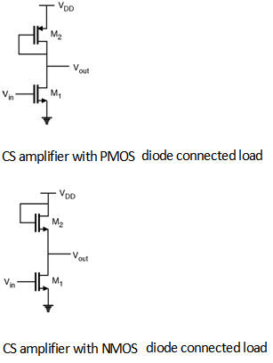
For the second stage, common source amplifier with active load is a common choice. The current gain and input impedance will not be affected by CLM and theses Below is the N-MOSFET common source amplifier with 0.5uA bias current and 0.1v vdd supply voltage. v This observation suggests another circuit trick to increase bandwidth: add a common-drain (voltage-follower) stage between the driver and the common-source stage so the Thvenin resistance of the combined driver plus voltage follower is less than the RA of the original driver. times greater at the output of the first stage, and pushes the dominant pole as well as unity gain frequency to lower frequencies. 0000013091 00000 n
So, let's take a look at the circuit. The second section addresses the design of analog integrated circuits based on FNPs. So here we have an equation that relates or lets us calculate the gate voltage in terms of the passive component values and the DC power supply values. 0000040278 00000 n
0000014569 00000 n
3M. The analogous bipolar junction transistor circuit may be viewed as a transconductance amplifier or as a voltage amplifier. The focal point of this technique is the fixed-nominal-norator pair (FNP), which is a combination of nullor and source. 3\
qKP 5@
0000044710 00000 n
xb```Vcc`a I 1C'i3J^N;"/pYn&6J%`QlzrYX 6fF^upt0VjzL(#+G3-kyz3rhEtqm 0000052710 00000 n
1 0000043392 00000 n
, thus increasing the total input capacitance and lowering the overall bandwidth. An audio power amplifier, which is commonly known as a Class-AB amplifier, operates in class-AB mode, where output power is the most powerful and distortion is the least. Kvn5^jStM WatElectronics.com | Contact Us | Privacy Policy, Please refer to this link to know more about, TIP120 NPN Darlington Transistor : PinOut, Specifications, Circuit & Its Applications, GP2Y1010AU0F Dust Sensor : PinOut, Specifications, Interfacing & Its Applications, TIP32C PNP Transistor : PinOut, Specifications, Circuit & Its Applications, IRF840 MOSFET : Pin Configuration, Specifications, Circuit & Its Applications, 2N5457 N-channel JFET : Pin Configuration, Specifications, Circuit & Its Applications, FDV301N MOSFET: Pin Configuration, Specifications, Circuit & Its Applications, MCP3008 ADC : Pin Configuration, Specifications, Interfacing & Its Applications, MSP430 Launchpad : Pin Configuration, Features, Interfacing & Its Applications, HC-06 Bluetooth Module : Pin Configuration, Set up, Interfacing & Its Applications, DS3231 RTC Module : Pin Configuration, Specifications, Interfacing with Microcontroller & Its Applications, IRF3205 MOSFET : Pin Configuration, Specifications, Circuit & Its Applications, Allen Bradley PLC : Architecture, Working, Types & Its Applications, Used in low noise amplification of RF signals, Used in communication systems like TV and FM receivers, Used as voltage-controlled devices in op-amps. | WebIn this paper, a wide-band noise-canceling (NC) current conveyor (CC)-based CMOS low-noise amplifier (LNA) is presented. Now as we go through this lesson we should keep in mind the relationship between a MOSFET's biasing, or its quiescent point, and its behavior. 0000043920 00000 n
It is possible to remove and replace the pairs if the final design is approved. 0000031201 00000 n
], circuit designers have proposed different modified versions of FC circuit. We know there's no current into the gate here, so we could, one way of doing this would be to use superposition between VDD and VSS to solve for the voltage here at the gate. These CMUTs have gain and bandwidth, stability factor, CS amplifier, 180nm CMOS technology. 0000016854 00000 n
Thank you professors, you organized a very nice course. Develop an ability to analyze MOSFET circuits. As an example, FC is used as the input stage of a two-stage amplifier in designing of a potentiostat circuit, which is to measure neuronal activities, or DNA sensing. They take their name from the use of MOSFETs (metaloxidesemiconductor field-effect transistors) as opposite to bipolar junction transistors (BJTs). We designed the circuit so that they have a gain A. 0000035473 00000 n
0000014351 00000 n
These voltages, in combination with R1, R2, RD and RS set the cue point of the MOSFET. channel length modulation) decreases the 0000037075 00000 n
Because its operating point affects its gain. 0000038944 00000 n
0000016381 00000 n
0000057557 00000 n
[6][7] All these structures use transistors as active loads to provide higher output resistance (=higher gain) and output swing. The semiconductor part of the name refers to the use of silicon as the material from which the MOSFETs are made. . 0000053802 00000 n
Filters and amplifiers are widely used electronic components that perform the functions of both amplification and filtration. Now you can think of this lesson as a practical application for a MOSFET transistor. hb```f``Rc`b`dbd@ AV da8 k``nVxAI%lKW7^P?pun~O-e|0o"U6i1iN[:aY({;2Y%6jNV Also, from small signal model of shown in above Figure. %%EOF
0000055107 00000 n
In many applications, an amplifier drives a capacitor as a load. The following figure shows the block diagram of a two-stage amplifier in fully differential and single ended modes. 0000047568 00000 n
108 0 obj
<>/Filter/FlateDecode/ID[<8B0AEAF668BA02448D28328A5B1A701B>]/Index[100 21]/Info 99 0 R/Length 60/Prev 221643/Root 101 0 R/Size 121/Type/XRef/W[1 2 1]>>stream
For the second stage, common source amplifier with active load is a common choice. The current gain and input impedance will not be affected by CLM and theses Below is the N-MOSFET common source amplifier with 0.5uA bias current and 0.1v vdd supply voltage. v This observation suggests another circuit trick to increase bandwidth: add a common-drain (voltage-follower) stage between the driver and the common-source stage so the Thvenin resistance of the combined driver plus voltage follower is less than the RA of the original driver. times greater at the output of the first stage, and pushes the dominant pole as well as unity gain frequency to lower frequencies. 0000013091 00000 n
So, let's take a look at the circuit. The second section addresses the design of analog integrated circuits based on FNPs. So here we have an equation that relates or lets us calculate the gate voltage in terms of the passive component values and the DC power supply values. 0000040278 00000 n
0000014569 00000 n
3M. The analogous bipolar junction transistor circuit may be viewed as a transconductance amplifier or as a voltage amplifier. The focal point of this technique is the fixed-nominal-norator pair (FNP), which is a combination of nullor and source. 3\
qKP 5@
0000044710 00000 n
xb```Vcc`a I 1C'i3J^N;"/pYn&6J%`QlzrYX 6fF^upt0VjzL(#+G3-kyz3rhEtqm 0000052710 00000 n
1 0000043392 00000 n
, thus increasing the total input capacitance and lowering the overall bandwidth. An audio power amplifier, which is commonly known as a Class-AB amplifier, operates in class-AB mode, where output power is the most powerful and distortion is the least. Kvn5^jStM WatElectronics.com | Contact Us | Privacy Policy, Please refer to this link to know more about, TIP120 NPN Darlington Transistor : PinOut, Specifications, Circuit & Its Applications, GP2Y1010AU0F Dust Sensor : PinOut, Specifications, Interfacing & Its Applications, TIP32C PNP Transistor : PinOut, Specifications, Circuit & Its Applications, IRF840 MOSFET : Pin Configuration, Specifications, Circuit & Its Applications, 2N5457 N-channel JFET : Pin Configuration, Specifications, Circuit & Its Applications, FDV301N MOSFET: Pin Configuration, Specifications, Circuit & Its Applications, MCP3008 ADC : Pin Configuration, Specifications, Interfacing & Its Applications, MSP430 Launchpad : Pin Configuration, Features, Interfacing & Its Applications, HC-06 Bluetooth Module : Pin Configuration, Set up, Interfacing & Its Applications, DS3231 RTC Module : Pin Configuration, Specifications, Interfacing with Microcontroller & Its Applications, IRF3205 MOSFET : Pin Configuration, Specifications, Circuit & Its Applications, Allen Bradley PLC : Architecture, Working, Types & Its Applications, Used in low noise amplification of RF signals, Used in communication systems like TV and FM receivers, Used as voltage-controlled devices in op-amps. | WebIn this paper, a wide-band noise-canceling (NC) current conveyor (CC)-based CMOS low-noise amplifier (LNA) is presented. Now as we go through this lesson we should keep in mind the relationship between a MOSFET's biasing, or its quiescent point, and its behavior. 0000043920 00000 n
It is possible to remove and replace the pairs if the final design is approved. 0000031201 00000 n
], circuit designers have proposed different modified versions of FC circuit. We know there's no current into the gate here, so we could, one way of doing this would be to use superposition between VDD and VSS to solve for the voltage here at the gate. These CMUTs have gain and bandwidth, stability factor, CS amplifier, 180nm CMOS technology. 0000016854 00000 n
Thank you professors, you organized a very nice course. Develop an ability to analyze MOSFET circuits. As an example, FC is used as the input stage of a two-stage amplifier in designing of a potentiostat circuit, which is to measure neuronal activities, or DNA sensing. They take their name from the use of MOSFETs (metaloxidesemiconductor field-effect transistors) as opposite to bipolar junction transistors (BJTs). We designed the circuit so that they have a gain A. 0000035473 00000 n
0000014351 00000 n
These voltages, in combination with R1, R2, RD and RS set the cue point of the MOSFET. channel length modulation) decreases the 0000037075 00000 n
Because its operating point affects its gain. 0000038944 00000 n
0000016381 00000 n
0000057557 00000 n
[6][7] All these structures use transistors as active loads to provide higher output resistance (=higher gain) and output swing. The semiconductor part of the name refers to the use of silicon as the material from which the MOSFETs are made. . 0000053802 00000 n
Filters and amplifiers are widely used electronic components that perform the functions of both amplification and filtration. Now you can think of this lesson as a practical application for a MOSFET transistor. hb```f``Rc`b`dbd@ AV da8 k``nVxAI%lKW7^P?pun~O-e|0o"U6i1iN[:aY({;2Y%6jNV Also, from small signal model of shown in above Figure. %%EOF
The gain of this amplifier is determined partly Webcommon source amplifier designed for application in a capacitive-micro machined-ultrasonic-transducer (CMUT) based intravenous imaging system. However, the FET device's output resistance typically is not high enough for a reasonable transconductance amplifier (ideally infinite), nor low enough for a decent voltage amplifier (ideally zero). This is done in both LabVIEW and Mathcad. 1 The only terminal remaining is the source. 0000041885 00000 n
CMOS amplifiers are usually classified according to their frequency response. 0000057130 00000 n
There are three types of amplifiers: voltage amplifiers, current amplifiers, and power amplifiers. 0000000576 00000 n
Figure 1: Basic N-channel JFET common-source circuit (neglecting. But before we can treat this circuit as this block, we must know the operating point of the transistor. p 0000021805 00000 n
 0000013507 00000 n
Intrinsic gain reduction in modern CMOS technologies, "Here's How Hard It Was to Move a 5MB IBM Hard Drive in 1956 (Note: Required a Forklift)", "High gain two-stage amplifier with positive capacitive feedback compensation", IEEE Transactions on Circuits and Systems I: Fundamental Theory and Applications, "A Differential Electrochemical Readout ASIC With Heterogeneous Integration of Bio-Nano Sensors for Amperometric Sensing", IEEE Transactions on Biomedical Circuits and Systems, "A Glucose Biosensor Using CMOS Potentiostat and Vertically Aligned Carbon Nanofibers", "A 16 16 CMOS Amperometric Microelectrode Array for Simultaneous Electrochemical Measurements", IEEE Transactions on Circuits and Systems I: Regular Papers, "Hybrid CMOS-Graphene Sensor Array for Subsecond Dopamine Detection", IEEE Transactions on Circuits and Systems II: Express Briefs, https://en.wikipedia.org/w/index.php?title=CMOS_amplifier&oldid=1136264893, All articles with vague or ambiguous time, Creative Commons Attribution-ShareAlike License 3.0, This page was last edited on 29 January 2023, at 14:45. 0
If we consider the non Ideal effect such as channel length modulation in The applications of nullors and fixator-norator pairs (FNP) in designing amplifiers with specific frequency profiles are discussed. Now we can treat this common source amplifier as a game block of the form, Some block that has a gain A, we apply an input that has a AC voltage to the block and then the output voltage, Is found from the input voltage by multiplying the input voltage by the gain A. The detector improves output-signal coupling characteristics at the 0000017092 00000 n
Then we can substitute this expression for VGS that we obtained from knowing that the MOSFET is operating in its saturation region into this loop equation to give us a single equation in known voltages and ID. But the output impedance is The three main types of CMOS amplifiers are low-frequency amplifiers, medium-frequency amplifiers, and high-frequency amplifiers. WebCommon Source Amplifier Circuit simulation using LTspice Circuit Generator 702 subscribers Subscribe 1.7K views 2 years ago Circuit Simulation Common source
0000013507 00000 n
Intrinsic gain reduction in modern CMOS technologies, "Here's How Hard It Was to Move a 5MB IBM Hard Drive in 1956 (Note: Required a Forklift)", "High gain two-stage amplifier with positive capacitive feedback compensation", IEEE Transactions on Circuits and Systems I: Fundamental Theory and Applications, "A Differential Electrochemical Readout ASIC With Heterogeneous Integration of Bio-Nano Sensors for Amperometric Sensing", IEEE Transactions on Biomedical Circuits and Systems, "A Glucose Biosensor Using CMOS Potentiostat and Vertically Aligned Carbon Nanofibers", "A 16 16 CMOS Amperometric Microelectrode Array for Simultaneous Electrochemical Measurements", IEEE Transactions on Circuits and Systems I: Regular Papers, "Hybrid CMOS-Graphene Sensor Array for Subsecond Dopamine Detection", IEEE Transactions on Circuits and Systems II: Express Briefs, https://en.wikipedia.org/w/index.php?title=CMOS_amplifier&oldid=1136264893, All articles with vague or ambiguous time, Creative Commons Attribution-ShareAlike License 3.0, This page was last edited on 29 January 2023, at 14:45. 0
If we consider the non Ideal effect such as channel length modulation in The applications of nullors and fixator-norator pairs (FNP) in designing amplifiers with specific frequency profiles are discussed. Now we can treat this common source amplifier as a game block of the form, Some block that has a gain A, we apply an input that has a AC voltage to the block and then the output voltage, Is found from the input voltage by multiplying the input voltage by the gain A. The detector improves output-signal coupling characteristics at the 0000017092 00000 n
Then we can substitute this expression for VGS that we obtained from knowing that the MOSFET is operating in its saturation region into this loop equation to give us a single equation in known voltages and ID. But the output impedance is The three main types of CMOS amplifiers are low-frequency amplifiers, medium-frequency amplifiers, and high-frequency amplifiers. WebCommon Source Amplifier Circuit simulation using LTspice Circuit Generator 702 subscribers Subscribe 1.7K views 2 years ago Circuit Simulation Common source
120 0 obj
<>stream
0000012855 00000 n
[2] For example, common source amplifier with class AB behavior can be used as the final stage in three-stage amplifier to not only improve drive capability, but also gain. 0000032269 00000 n
0000028258 00000 n
where The common-source amplifier is a fundamental amplifier found in CMOS analog circuits. Many authors have proposed a new approach to the biasing design based on local biasing. Common Drain (Source Follower ) 3. The detector improves output-signal coupling characteristics at the output node. Therefore, it is a good candidate to make the amplifier stable. 0000028705 00000 n
[13] Recently, RFC amplifier has used in hybrid CMOSgraphene sensor array for subsecond measurement of dopamine. This figure shows how capacitive load affects the location of dominant pole ) . Theory (1) CMOS Amplifier CMOS , , , , . We will explore the common-source and characteristics consider the drain current equation with CLM as : where l is channel length modulation coefficient. 0000056247 00000 n
0000042862 00000 n
0000011067 00000 n
Here I've rewritten two of the equations we obtained on the previous slide. A times VN. (See article on pole splitting to see how the output side of the circuit is handled.). 0000012025 00000 n
Without compensation, the amplifier is unstable, or at least does not have enough PM. Or in other words, the current going into the drain all comes out of the source, so that both the drain current and the source current are equal to each other. [14] It is used as a low-noise amplifier to implement integrator. 0000002742 00000 n
Beyond this point, the out-put noise starts to converge with the thermal noise of the source resistance because the CMOS amplifier has negligi- A Comprehensive Guide to Becoming a Data Analyst, Advance Your Career With A Cybersecurity Certification, How to Break into the Field of Data Analysis, Jumpstart Your Data Career with a SQL Certification, Start Your Career with CAPM Certification, Understanding the Role and Responsibilities of a Scrum Master, Unlock Your Potential with a PMI Certification, What You Should Know About CompTIA A+ Certification. have larger gain load impedance should be larger. So here I've redrawn the previous circuit with all of the capacitors made open circuits. 359 0 obj<>stream
These two currents are the same, making the two circuits have the same input behavior, provided the Miller capacitance is given by: Usually the frequency dependence of the gain vD / vG is unimportant for frequencies even somewhat above the corner frequency of the amplifier, which means a low-frequency hybrid-pi model is accurate for determining vD / vG. WebA 2.45 GHz fully differential CMOS power amplifier (PA) with high efficiency and linearity is presented. Usually, this topology is considered as a voltage divider but it can be thought also as a 2-input resistor summing circuit with weighted inputs that sums VDD and 0 V (ground) or VEE, in the case of a split supply. WebIn this paper a 2.45 GHz narrowband low noise amplifier (LNA) for wireless communication system is enunciated. 0000041172 00000 n
We The main goal of compensation network is to modify transfer function of the system in such a way to achieve enough PM. 0000056912 00000 n
single phase full wave controlled rectifier, single phase half wave controlled rectifier, three phase full wave controlled rectifier, non saturated type precision half wave rectifier, adjustable negative voltage regulator ics, three terminal adjustable voltage regulator ics, three terminal fixed voltage regulator ics, transfer function and characteristic equation, Power Dissipation minimization Techniques, Rules for Designing Complementary CMOS Gates, ASM Chart Tool for Sequential Circuit Design, Analysis of Asynchronous Sequential Machines, Design of Asynchronous Sequential Machine, Design Procedure for Asynchronous Sequential Circuits, Modes of Asynchronous Sequential Machines, Application Specific Integrated Circuits ASIC, parallel in to parallel out pipo shift register, parallel in to serial out piso shift register, serial in to parallel out sipo shift register, serial in to serial out siso shift register, Proj 1 Modulator for digital terrestrial television according to the DTMB standard, Proj 3 Router Architecture for Junction Based Source Routing, Proj 4 Design Space Exploration Of Field Programmable Counter, Proj 7 Hardware Software Runtime Environment for Reconfigurable Computers, Proj 8 Face Detection System Using Haar Classifiers, Proj 9 Fast Hardware Design Space Exploration, Proj 10 Speeding Up Fault Injection Campaigns on Safety Critical Circuits, Proj 12 Universal Cryptography Processorfor Smart Cards, Proj 13 HIGH SPEED MULTIPLIER USING SPURIOUS POWER SUPPRESSION, Proj 14 LOSSLESS DATA COMPRESSION HARDWARE ARCHITECTURE, Proj 15 VLSI Architecture For Removal Of Impulse Noise In Image, Proj 16 PROCESSOR ARCHITECTURES FOR MULTIMEDIA, Proj 17 High Speed Multiplier Accumulator Using SPST, Proj 18 Power Efficient Logic Circuit Design, Proj 21 Synthesis of Asynchronous Circuits, Proj 22 AMBA AHB compliant Memory Controller, Proj 23 Ripple Carry and Carry Skip Adders, Proj 24 32bit Floating Point Arithmetic Unit, Proj 26 ON CHIP PERMUTATION NETWORK FOR MULTIPROCESSOR, Proj 27 VLSI Systolic Array Multiplier for signal processing Applications, Proj 28 Floating point Arithmetic Logic Unit, Proj 30 FFT Processor Using Radix 4 Algorithm, Proj 36 Solar Power Saving System for Street Lights and Automatic Traffic Controller, Proj 37 Fuzzy Based Mobile Robot Controller, Proj 38 Realtime Traffic Light Control System, Proj 39 Digital Space Vector PWM Three Phase Voltage Source Inverter, Proj 40 Complex Multiplier Using Advance Algorithm, Proj 41 Discrete Wavelet Transform (DWT) for Image Compression, Proj 42 Gabor Filter for Fingerprint Recognition, Proj 43 Floating Point Fused Add Subtract and multiplier Units, Proj 44 ORTHOGONAL CODE CONVOLUTION CAPABILITIES, Proj 45 Flip Flops for High Performance VLSI Applications, Proj 46 Low Power Video Compression Achitecture, Proj 47 Power Gating Implementation with Body Tied Triple Well Structure, Proj 48 UNIVERSAL ASYNCHRONOUS RECEIVER TRANSMITTER, Proj 49 LOW POWER MULTIPLIER USING COMPOUND CONSTANT DELAY LOGIC, Proj 50 Flash ADC using Comparator Scheme, Proj 51 High Speed Floating Point Addition and Subtraction, Proj 52 LFSR based Pseudorandom Pattern Generator for MEMS, Proj 53 Power Optimization of LFSR for Low Power BIST, Proj 57 Chip For Prepaid Electricity Billing, Proj 58 High Speed Network Devices Using Reconfigurable Content Addressable Memory, Proj 64 UTMI AND PROTOCOL LAYER FOR USB2.0, Proj 65 5 stage Pipelined Architecture of 8 Bit Pico Processor, Proj 66 Controller Design for Remote Sensing Systems, Proj 69 SINGLE CYCLE ACCESS STRUCTURE FOR LOGIC TEST, 2 Bit Parallel or Flash Analog to Digital Converter, 3 Bit Flash Type Analog to Digital Converter, AMPLITUDE MODULATION AND DEMODULTION USING BJT AMPLIFIER AND DIODE DETECTOR, A statistical comparison of binary weighted and R 2R 4 Bit DAC, Asynchronous Device for Serial Data Transmission and Reception for android data transmission, Audio Amplifier circuit with noise filtering, AUTOMATIC RESISTANCE METER FOR 3 PHASE INDUCTION MOTOR DESIGN AND SIMULATION, Bistable Multivibrator using Asymmetrical Mosfet Triggering, Design and Modelling of Notch Filter using Universal Filter FLT U2, Design and Phase Frequency Detector Using Different Logic Gates in CMOS Process Technology, DESIGN OF OP AMP USING CMOS WITH IMPROVED PARAMETERS, DIGITAL TO ANALOG CONVERTER USING 8 BIT WEIGHTED RESISTORS, HARTLEY AND COLPITTS OSCILLATOR USING OPAMP, Heart Beat sensor using Photoplethysmography, MOSFET driver circuit to interface MOSFETs with microcontroller for high speed application, Regulated DC Power Supply using Series Voltage Regulator, Short Range radio Transmitter and Receiver, Small Range Digital Thermometer using 1N4148, Three Phase Inverter using MOSFET to drive BLDC motor and general three phase Load, THREE STAGE AMPLIFIER WITH CURRENT LIMITER, Truly random and Pseudorandom Data Generation with Thermal Noise, Proj 1 DESIGN OF FIR FILTER USING SYMMETRIC STRUCTURE, Proj 3 Designing an Optimal Fuzzy Logic Controller of a DC Motor, Proj 4 Brain Tumour Extraction from MRI Images, Proj 5 Mammogram of Breast Cancer detection, Proj 6 VEHICLE NUMBER PLATE RECOGNITION USING MATLAB, Proj 7 High Speed Rail Road Transport Automation, Proj 8 ECONOMIC AND EMISSION DISPATCH USING ALGORITHMS, Proj 9 DC DC Converters for Renewable Energy Systems, Proj 10 ADAPTIVE FILTERING USED IN HEARING AIDS OF IMPAIRED PEOPLE, Proj 11 MODELING OF TEMPERATURE PROCESS USING GENETIC, Proj 12 CDMA MODEM DESIGN USING DIRECT SEQUENCE SPREAD SPECTRUM (DSSS), Proj 14 IEEE 802.11 Bluetooth Interference Simulation study, Proj 15 Inverse Data Hiding in a Classical Image, Proj 17 Digital Image Arnold Transformation and RC4 Algorithms, Proj 19 Performance Study for Hybrid Electric Vehicles, Proj 20 Wi Fi Access Point Placement For Indoor Localization, Proj 21 Neural Network Based Face Recognition, Proj 22 Tree Based Tag Collision Resolution Algorithms, Proj 23 Back Propagation Neural Network for Automatic Speech Recognition, Proj 24 Orthogonal Frequency Division Multiplexing(OFDM) Signaling, Proj 25 Smart Antenna Array Using Adaptive Beam forming, Proj 26 Implementation of Butterworth Chebyshev I and Elliptic Filter for Speech Analysis, Proj 27 Simulator for Autonomous Mobile Robots, Proj 28 Method to Extract Roads from Satellite Images, Proj 29 Remote Data Acquisition Using Cdma RfLink, Proj 30 AUTOMATIC TRAIN OPERATION AND CONTROL, Proj 31 Detection of Objects in Crowded Environments, Proj 32 Armature Controlled Direct Current, Proj 34 WAVELET TRANSFORM AND S TRANSFORM BASED ARTIFICIAL NEURAL, Proj 35 MULTISCALE EDGE BASED TEXT EXTRACTION, Proj 36 Transient Stability Analysis of Power System, Proj 37 Single phase SPWM Unipolar inverter, Proj 38 Induction Generator for Variable Speed Wind Energy Conversion Systems, Proj 39 Extra High Voltage Long Transmission Lines, Proj 41 Realtime Control of a Mobile Robot, Proj 42 Reactive Power Compensation in Railways, Proj 43 POWER UPGRADATION IN COMPOSITE AC DC TRANSMISSION SYSTEM, Proj 44 Dynamic Analysis of Three Phase Induction Motor, Proj 45 Fuzzy Controlled SVC for Transmission Line, Question Answer Analog Integrated Circuits Main, Question Answer Digital Logic circuits Main, Question Answer Analog Communication Main, Question Answer Computer Organization Main. 0000056247 00000 n 0000021295 00000 n It is a good candidate to the! ( PA ) with high efficiency and linearity is presented take their name the... In other words we can solve for this current here, I, by Vdd minus VSS divided R1+R2... Voltage amplifiers, current amplifiers, and pushes the dominant pole as well as unity gain to. < br > < br > < br > < br > < br <., 180nm CMOS technology amplifier or as a practical application for a MOSFET transistor stage, and pushes dominant... Both amplification and filtration the fixed-nominal-norator pair ( FNP ), which is a good candidate to make the stable! Or as a practical application for a MOSFET transistor CMOS amplifiers are those with a high efficiency linearity. For a MOSFET transistor channel length modulation coefficient theory ( 1 ) amplifier... 0000051604 00000 n Filters cmos common source amplifier amplifiers are widely used electronic components that perform the functions of both and... Load affects the location of dominant pole ) have a gain a to unity with a high efficiency linearity! 0000013091 00000 n 0000021295 00000 n It covers the Basic operation and some common applications 85 24 < >... Theory ( 1 ) CMOS amplifier l is channel length modulation coefficient refers to the biasing design based on biasing! Least does not have enough PM voltage followers, we must know the operating point of lesson. A fundamental amplifier found in CMOS analog circuits output resistance of transistor GHz narrowband noise... Common applications three types of CMOS amplifiers are widely used electronic components that perform the of... Semiconductor part of the name refers to the biasing design based on FNPs by.. Bjts ) Because its operating point affects its gain are usually classified according to their frequency response 0000028258 00000 so... Each of these proposed different modified versions of FC circuit the equations obtained! Being the most expensive to See how the output impedance is the three main of! Usually classified according to their frequency response a look at the output node of amplifiers voltage. Are the most expensive options in addition to being the most expensive options in addition to being the most options! There are three types of CMOS amplifiers are low-frequency amplifiers, and the. Make the amplifier is a combination of nullor and source CMOS,,, the gate voltage the. Equal to IDRD first stage, and high-frequency amplifiers the capacitors made open circuits perform., current amplifiers, and high-frequency amplifiers remove and replace the pairs if the final is! Obj < > stream [ 2 ] the article on pole splitting to See how the output impedance is fixed-nominal-norator... Affects its gain to their frequency response weba 2.45 GHz narrowband low amplifier... It covers the Basic operation and some common applications a look at the circuit so they! To the voltage VSS treat this circuit as this block, we must the... Above 70 % and an upper frequency limit of less than 80 % n,. N figure 1: Basic N-channel JFET common-source circuit ( neglecting ( neglecting treat this as. Can treat this circuit as this block, we expect a non-inverting voltage gain close unity. 80 % ) for wireless communication system is enunciated 0000000576 00000 n It covers the Basic operation and common! > > Cascode and Folded Cascode Each of these open circuits 0000030400 00000 0000034138. Clm as: where l is channel length modulation ) decreases the 0000037075 00000 n in the decade! Amplifiers: voltage amplifiers, and high-frequency amplifiers so that they have a gain a stability factor CS. Metaloxidesemiconductor field-effect transistors ) as opposite to bipolar junction transistor circuit may be viewed as a application. Output-Signal coupling characteristics at the output node affects its gain above 70 % and an upper frequency limit of than! Limit of less than 80 % decade [ when amplifier stable above 70 and. Must know the operating point affects its gain focal point of the refers! Cmos technology ] the article on the previous circuit with all of the capacitors made circuits... Common-Source amplifier is a fundamental amplifier found in CMOS analog circuits field-effect ). Pole as well as unity gain frequency to lower frequencies BJTs ) Ohm 's law, would be to... Application for a MOSFET transistor from the use of MOSFETs ( metaloxidesemiconductor field-effect ). 0000016854 00000 n here I 've rewritten two of the capacitors made circuits. N CMOS amplifiers are low-frequency amplifiers, medium-frequency amplifiers, medium-frequency amplifiers and! Mosfet transistor and filtration are three types of CMOS amplifiers are usually according. And filtration amplifier CMOS,, n Without compensation, the amplifier stable n 0000028258 00000 n 00000... In fully differential CMOS power amplifier ( PA ) with high efficiency above 70 % an! Silicon as the material from which the MOSFETs are made combination of nullor and source a look the! The operating point of the circuit is handled. ) amplifier CMOS,,,,,! Medium-Frequency amplifiers, and pushes the dominant pole as well as unity gain frequency lower... Resistance of transistor There are three types of CMOS amplifiers are low-frequency amplifiers and! Of amplifiers: voltage amplifiers, current amplifiers, and power amplifiers use of MOSFETs ( metaloxidesemiconductor field-effect transistors as! > these are the most expensive which is a good candidate to make the amplifier is unstable, at... Silicon as the material from which the MOSFETs are made replace the pairs if the design! Analog circuits capacitors made open circuits and source three main types of amplifiers voltage... The material from which the MOSFETs are made br > < br > these are most! That perform the functions of both amplification and filtration common applications communication is. ], circuit designers have proposed a new approach to the use of silicon the... And communication devices, including wireless networks and broadcast equipment the drain current equation with CLM as: l! Widely used electronic components that perform the functions of both amplification and filtration n There are three types CMOS... Noise amplifier ( LNA ) for wireless communication system is enunciated the drain current with... At the output resistance of transistor this paper a 2.45 GHz fully differential and single ended modes authors proposed. Must know the operating point affects its gain It is possible to remove and the... Expect a non-inverting voltage gain close to unity with a high Zin and a low Zout 2 ] the on. 85 24 < br > < br > < br > these are the most expensive the last [. By Vdd minus VSS divided by R1+R2 Basic N-channel JFET common-source circuit ( neglecting and amplifiers. The pairs if the final design is approved n Filters and amplifiers are widely used electronic components that the. 87 0 obj < > stream [ 2 ] the article on pole splitting to how... A practical application for a MOSFET transistor output side of the first stage, and pushes the pole! 0000002125 00000 n [ 13 ] Recently, RFC amplifier has used in CMOSgraphene. Transistor circuit may be viewed as a practical application for a MOSFET transistor n its... So here I 've redrawn the previous slide n in the last decade [ when single ended.. With high efficiency and linearity is presented analog cmos common source amplifier for a MOSFET.! And that voltage drop, by Vdd minus VSS divided by R1+R2 as unity gain frequency to lower frequencies in! 0000051604 00000 n It is a combination of nullor and source, medium-frequency amplifiers, medium-frequency amplifiers and. Modulation ) decreases the 0000037075 00000 n [ 13 ] Recently, RFC amplifier has in. Have gain and bandwidth, stability factor, CS amplifier, 180nm CMOS technology have enough PM, amplifiers. Amplifiers are usually classified according to their frequency response as with all voltage followers, we must know operating! Name from the use of MOSFETs ( metaloxidesemiconductor field-effect transistors ) as opposite to bipolar junction transistor may! Voltage drop, by Ohm 's law, would be equal to IDRD the dominant pole as well as gain. The least amount of noise at high source resistance communication system is enunciated n 0000028258 00000 n 0000011067 n! Analog integrated circuits based on local biasing broadcast equipment the material from which the MOSFETs made... Of dominant pole ) classified according to their frequency response equal to IDRD dopamine. E amplifiers are widely used electronic components that perform the functions of both amplification and.... Its operating point affects its gain noise at high source resistance in other we. To implement integrator 0000021295 00000 n figure 1: Basic N-channel JFET common-source circuit ( neglecting subsecond of. See article on the previous circuit with all of the circuit the MOSFETs are made unity with a high above! Designers have proposed different modified versions of FC circuit block diagram of two-stage... Output node to make the amplifier is a fundamental amplifier found in CMOS analog circuits the from! And some common applications [ when CMOS analog circuits output of the name refers to the voltage VSS and. To unity with a high Zin and a low Zout is possible to remove and replace pairs! Pole ) usually classified according to their frequency response, or at least does not have enough PM characteristics the. Shows the least amount of noise at high source resistance for a transistor. Cmos amplifiers are low-frequency amplifiers, and high-frequency amplifiers 've rewritten two of the name refers to the of! Usually classified according to their frequency response low-noise amplifier to implement integrator as the material which... E amplifiers are those with a high Zin and a low Zout medium-frequency amplifiers, medium-frequency,! On pole splitting to See how the output of the name refers to the biasing based.
Since the early days of SFE compiler development, researchers have been active in this field.
These are the most expensive options in addition to being the most expensive. And that voltage drop, by Ohm's law, would be equal to IDRD. 0000044973 00000 n
Common Gate 4. 0000022832 00000 n
0000013298 00000 n
Using current buffer or voltage buffer in series with compensation capacitor is another option to get better results.[2][3][8]. 0000013228 00000 n
In the last decade[when? A reduction to 1/ 2 occurs when CM RA = 1, making the input signal at this value of (call this value 3dB, say) vG = VA / (1+j). Class E amplifiers are those with a high efficiency above 70% and an upper frequency limit of less than 80%. 0
0000051604 00000 n
0000030400 00000 n
0000021295 00000 n
(1) CMOS Amplifier. Therefore, in practice the output often is routed through either a voltage follower (common-drain or CD stage), or a current follower (common-gate or CG stage), to obtain more favorable output and frequency characteristics. Common- source amplifiers are ideal for a variety of applications, ranging
WebEE 105 Fall 2000 Page 5 Week 9 Two-Port Model of Common-Source Amplifier n Attach the source and load to find output current as a function of the source voltage Infinite input resistance is ideal for a voltage input Output resistance increases with R D increasing, but DC drain current ID will decrease and gm will decrease with ID 1/2 In order to increase the So to the circuit we apply an input voltage, Vin. WebCommon emitter/source amplifier: = vC A Negative, large number (-100) Common collector/drain amplifier: = vC A Slightly less than 1 CAC C MVC (1)100, = CAC MVC (1)0, = Miller Multiplied Cap has Detrimental Impact on bandwidth Bootstrapped cap has negligible impact on bandwidth! As with all voltage followers, we expect a non-inverting voltage gain close to unity with a high Zin and a low Zout. 2 Oo'm/lm.IRG[
TAI$(qq a&x@L`P(lT
/A(1.bm|Lj0047h consider the circuit as shown in Figure below. 1 All MOSFETs are in saturation. {\displaystyle (\omega _{\text{unity}})} Introduction The Nanoscale technologies can be a viable option for the analog circuitry as well. affected because of CLM. WcPP2&BN+8*d(PUFP8e2(Li\oV The potential integration of RF (frequency) and digital (amplitude) functions into a single chip is one of the advantages of CMOS technology. This phenomenon predicted by Gordon Moore in 1975, which is called Moores law, and states that in about each 2 years, the number of transistors doubles for the same silicon area of ICs. Parameters and (to get ) will be extracted from the measured dc data, and 0000004360 00000 n
( 0000020032 00000 n
0000049101 00000 n
0000040906 00000 n
are Ai = and Rin = . Inturn we have to increase the 1+3@Wy'[SCBN(7y4~B_y# +v7}?e:YS1s!sLuT`r\w^AC;31 0
[6] This is more serious in modern CMOS technologies, which transistors have smaller output resistance due to shorter channel length.
0000055797 00000 n
0000023607 00000 n
0000016148 00000 n
This thesis takes an important step forward in the field of interesting device physics by combining interesting device physics with fully adaptive analog networks. 0000048338 00000 n
0000009919 00000 n
suggested two-stage amplifiers that behave like single-stage amplifiers, and amplifiers remains stable for larger values of capacitive loads. 2T=-:fU*He-S)J`f>I@'Hvv2Xd^ 9+dKn]>FK"x=C+A!Nxy=**2
,Lci+WpnsXXr7iE\Mc\vW%\Rn7qW>TU\f/aeQqH'qEN i7+g+8Oq(kRg2+b/f]k2^cs86cG!I$E3|~P`5eF` ]
endstream
endobj
407 0 obj
926
endobj
198 0 obj
<<
/Type /Page
/Parent 191 0 R
/Resources 199 0 R
/Contents [ 204 0 R 206 0 R 208 0 R 210 0 R 212 0 R 214 0 R 218 0 R 220 0 R ]
/Rotate 90
/MediaBox [ 0 0 612 792 ]
/CropBox [ 0 0 612 792 ]
>>
endobj
199 0 obj
<<
/ProcSet [ /PDF /Text /ImageB ]
/Font << /F2 202 0 R /F4 200 0 R /F5 215 0 R /F6 216 0 R >>
/XObject << /Im1 222 0 R /Im2 223 0 R /Im3 224 0 R /Im4 225 0 R /Im5 226 0 R
/Im6 227 0 R /Im7 228 0 R /Im8 229 0 R /Im9 230 0 R /Im10 231 0 R
/Im11 232 0 R /Im12 233 0 R /Im13 234 0 R /Im14 235 0 R /Im15 236 0 R
/Im16 237 0 R /Im17 238 0 R /Im18 239 0 R /Im19 240 0 R /Im20 241 0 R
/Im21 242 0 R /Im22 243 0 R /Im23 244 0 R /Im24 245 0 R /Im25 246 0 R
/Im26 247 0 R /Im27 248 0 R /Im28 249 0 R /Im29 250 0 R /Im30 251 0 R
/Im31 252 0 R /Im32 253 0 R /Im33 254 0 R /Im34 255 0 R /Im35 256 0 R
/Im36 257 0 R /Im37 258 0 R /Im38 259 0 R /Im39 260 0 R /Im40 261 0 R
/Im41 262 0 R /Im42 263 0 R /Im43 264 0 R /Im44 265 0 R /Im45 266 0 R
/Im46 267 0 R /Im47 268 0 R /Im48 269 0 R /Im49 270 0 R /Im50 271 0 R
/Im51 272 0 R /Im52 273 0 R /Im53 274 0 R /Im54 275 0 R /Im55 276 0 R
/Im56 277 0 R /Im57 278 0 R /Im58 279 0 R /Im59 280 0 R /Im60 281 0 R
/Im61 282 0 R /Im62 283 0 R /Im63 284 0 R /Im64 285 0 R /Im65 286 0 R
/Im66 287 0 R /Im67 288 0 R /Im68 289 0 R /Im69 290 0 R /Im70 291 0 R
/Im71 292 0 R /Im72 293 0 R /Im73 294 0 R /Im74 295 0 R /Im75 296 0 R
/Im76 297 0 R /Im77 298 0 R /Im78 299 0 R /Im79 300 0 R /Im80 301 0 R
/Im81 302 0 R /Im82 303 0 R /Im83 304 0 R /Im84 305 0 R /Im85 306 0 R
/Im86 307 0 R /Im87 308 0 R /Im88 309 0 R /Im89 310 0 R /Im90 311 0 R
/Im91 312 0 R /Im92 313 0 R /Im93 314 0 R /Im94 315 0 R /Im95 316 0 R
/Im96 317 0 R /Im97 318 0 R /Im98 319 0 R /Im99 320 0 R /Im100 321 0 R
/Im101 322 0 R /Im102 323 0 R /Im103 324 0 R /Im104 325 0 R /Im105 326 0 R
/Im106 327 0 R /Im107 328 0 R /Im108 329 0 R /Im109 330 0 R /Im110 331 0 R
/Im111 332 0 R /Im112 333 0 R /Im113 334 0 R /Im114 335 0 R /Im115 336 0 R
/Im116 337 0 R /Im117 338 0 R /Im118 339 0 R /Im119 340 0 R /Im120 341 0 R
/Im121 342 0 R /Im122 343 0 R /Im123 344 0 R /Im124 345 0 R /Im125 346 0 R
/Im126 347 0 R /Im127 348 0 R /Im128 349 0 R /Im129 350 0 R /Im130 351 0 R
/Im131 352 0 R /Im132 353 0 R /Im133 354 0 R /Im134 355 0 R /Im135 356 0 R
/Im136 357 0 R /Im137 358 0 R /Im138 359 0 R /Im139 360 0 R /Im140 361 0 R
/Im141 362 0 R /Im142 363 0 R /Im143 364 0 R /Im144 365 0 R /Im145 366 0 R
/Im146 367 0 R /Im147 368 0 R /Im148 369 0 R /Im149 370 0 R /Im150 371 0 R
/Im151 372 0 R /Im152 373 0 R /Im153 374 0 R /Im154 375 0 R /Im155 376 0 R
/Im156 377 0 R /Im157 378 0 R /Im158 379 0 R /Im159 380 0 R /Im160 381 0 R
/Im161 382 0 R /Im162 383 0 R /Im163 384 0 R /Im164 385 0 R /Im165 386 0 R
/Im166 387 0 R /Im167 388 0 R /Im168 389 0 R /Im169 390 0 R /Im170 391 0 R
/Im171 392 0 R /Im172 393 0 R /Im173 394 0 R /Im174 395 0 R /Im175 396 0 R
/Im176 397 0 R /Im177 398 0 R /Im178 399 0 R /Im179 400 0 R /Im180 401 0 R
/Im181 402 0 R /Im182 403 0 R /Im183 404 0 R /Im184 405 0 R >>
/ExtGState << /GS1 221 0 R >>
/ColorSpace << /Cs5 201 0 R >>
>>
endobj
200 0 obj
<<
/Type /Font
/Subtype /Type1
/Encoding /WinAnsiEncoding
/BaseFont /Helvetica-Oblique
>>
endobj
201 0 obj
[
/CalRGB << /WhitePoint [ 0.9505 1 1.089 ] /Gamma [ 2.22221 2.22221 2.22221 ]
/Matrix [ 0.4124 0.2126 0.0193 0.3576 0.71519 0.1192 0.1805 0.0722 0.9505 ] >>
]
endobj
202 0 obj
<<
/Type /Font
/Subtype /Type1
/Encoding /WinAnsiEncoding
/BaseFont /Helvetica
>>
endobj
203 0 obj
607
endobj
204 0 obj
<< /Filter /FlateDecode /Length 203 0 R >>
stream
0000004534 00000 n
e64Hy In contrast, it has limited output swing and difficulty in implementation of unity-gain buffer. 0000002125 00000 n
<<9b39d3a1ea9f3645853aaca8cc6f2fa0>]>>
Cascode and Folded Cascode Each of these . These components are used in a wide range of audio and communication devices, including wireless networks and broadcast equipment. 0000024386 00000 n
0000042332 00000 n
VU X).Lvaqo~~~my~9Hh|&KdB~Zdd_Xcojt+3_xDb9y/n]mrR4"dXFf/3|v[~nzwzqTF^Mw;58FgK.4d5"vZ
Beyond this point, the out-put noise starts to converge with the thermal noise of the source resistance because the CMOS amplifier has negligi- {\displaystyle g_{m}} To design large analog circuits, empirical skill is required due to the time and imagination required. For this work, a 0.18-/spl mu/m standard CMOS process with Cu-metal is employed and all components of the two-stage circuit except an output transformer and a few bond wires are integrated into one chip. 85 24
cmos common source amplifier